
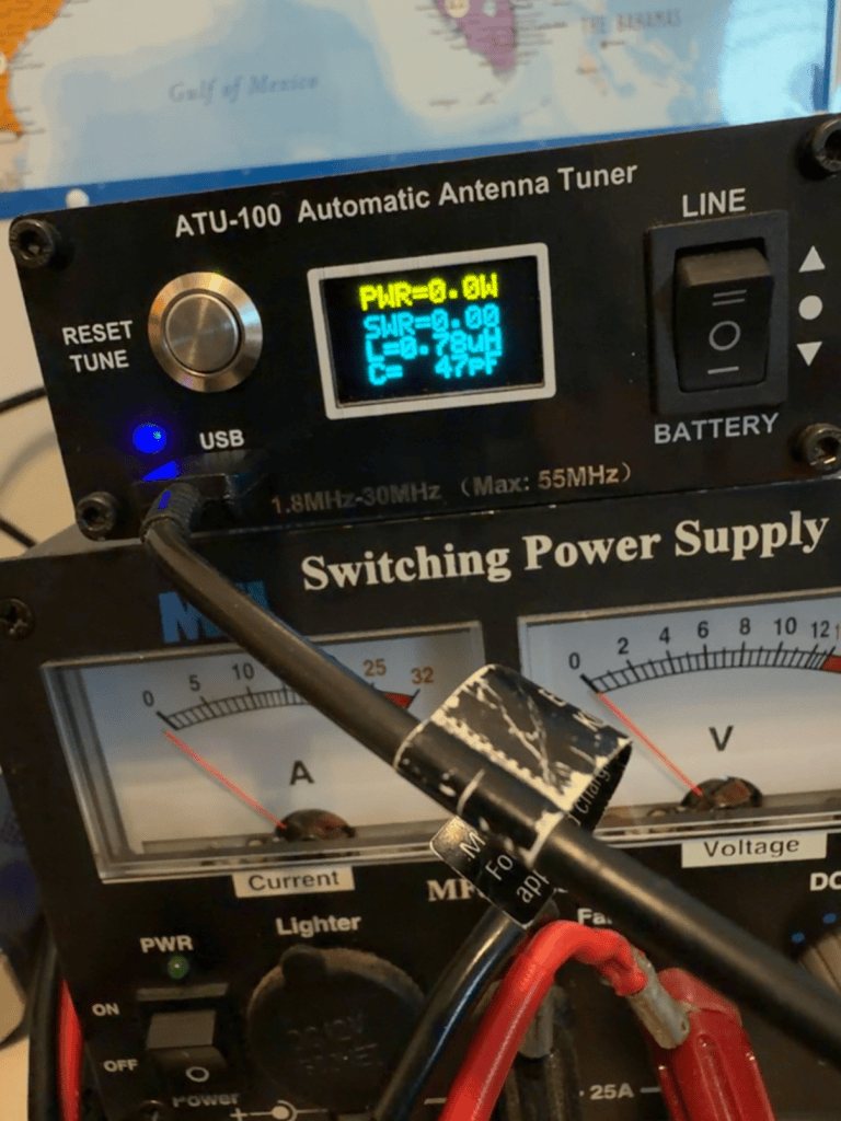
Listening on 7.207MHz. What does L and C tell me?
ChatGPT said:
That’s a good question, and it’s actually one of the more useful pieces of information the ATU-100 displays.
On your display while listening on 7.207 MHz, it shows approximately:
- L = 0.78 µH
- C = 47 pF
These are the values of inductance and capacitance that the tuner would (or did) switch into the matching network to transform your antenna’s impedance to something close to 50 Ω for the radio.
A few important points:
- L (Inductance)
- Measured in microhenries (µH).
- Produced by relays switching one or more inductors into the circuit.
- More inductance is generally needed when the antenna looks electrically short at that frequency.
- C (Capacitance)
- Measured in picofarads (pF).
- Produced by switched capacitors.
- The tuner uses just enough capacitance to complete the impedance transformation.
- These numbers are not antenna measurements.
They do not tell you:- your antenna’s resonant frequency,
- feedpoint impedance,
- whether the antenna is too long or too short.
What can you learn from them?
You can compare values across bands.
For example, if your 40 m EFHW shows:
| Band | L | C |
|---|---|---|
| 40 m | 0.8 µH | 47 pF |
| 20 m | 0 µH | 94 pF |
| 15 m | 2.3 µH | 0 pF |
you begin to see how much correction each band needs.
If you later shorten or lengthen the wire and the tuner suddenly needs much less L and C on 40 m, you’ve moved the antenna closer to resonance.
In your case
Since I know you’re using:
- Kenwood TS-430
- 40 m EFHW with a 49:1 unun
- ATU-100 while your RigExpert is away for repair
I’d mainly use these numbers as relative indicators, not absolute ones.
Once your RigExpert comes back, it will tell you the real story:
- actual resistance (R),
- reactance (X),
- SWR curve,
- and exactly whether the antenna is long or short.
The ATU-100 is essentially saying, “I needed 0.78 µH of inductance and 47 pF of capacitance to make this load look like 50 Ω.”
One more thing caught my eye in your photo: the tuner is showing PWR = 0.0 W and SWR = 0.00. That’s normal while you’re just listening. The L and C values shown are simply the last successful tuning solution it found—they aren’t changing while the receiver is idle.
If you’re interested, I can also explain how to use the direction and magnitude of the L and C values to make an educated guess about whether an antenna is electrically too long or too short, even without an antenna analyzer. It’s not perfect, but it’s a handy trick in the field during POTA.
Do these numbers indicate a large adjustment?
ChatGPT said:
In your case, no—I would call that a fairly modest adjustment.
The ATU-100 has a bank of switched inductors and capacitors. While the exact values depend on the firmware version, it can typically switch in roughly:
- Inductance: from 0 up to around 8–9 µH
- Capacitance: from 0 up to around 1,800–2,000 pF
Your reading was:
- L = 0.78 µH (less than 10% of the available inductance)
- C = 47 pF (only a tiny fraction of the available capacitance)
That tells me the tuner is making only a small correction, which is what I’d hope to see with a reasonably well-behaved 40 m EFHW and 49:1 transformer on its design band.
If, by comparison, you saw something like:
- L = 6–8 µH
- C = 800–1500 pF
then the tuner would be working much harder, suggesting the antenna is much farther from a 50 Ω match at that frequency.
A caveat with EFHWs
One thing to keep in mind is that an end-fed half-wave with a 49:1 unun doesn’t present exactly 50 Ω even when it’s resonant. The transformer is converting a high feedpoint impedance down toward 50 Ω, but the transformed impedance is often somewhere in the neighborhood of 40–70 Ω and varies with height, ground conditions, and wire length. So it’s perfectly normal for the tuner to make a small adjustment even on the antenna’s “home” band.
From everything you’ve told me over the past couple of weeks—using the ATU-100 while your RigExpert is being repaired and generally getting good results on 40 m—these values don’t raise any concerns for me. They suggest the tuner is just “touching up” the match rather than rescuing a poor antenna.
When your RigExpert comes back, it would be interesting to compare these tuner values with the analyzer’s measured R and X on 7.207 MHz. That comparison often helps develop an intuition for what the tuner is actually correcting.


Leave a Reply